
Multi-point crane product introduction :
The LX multi-pivot electric single-beam suspension crane adopts lightweight, modular and automated design. The lifting mechanism adopts the new Chinese electric hoist with safe and reliable performance technology, energy saving and environmental protection. The trolley running mechanism adopts a one-in-one drive device to drive separately, and the control adopts an advanced variable frequency speed control system. Cranes in the aerospace field include multi-pivot suspension cranes, suspension over-rail cranes and rotary lifting platforms .
Multi-point crane performance parameters:
Lifting capacity: 3 tons, 5 tons, 10 tons, 15 tons, 16 tons, 20 tons, 30 tons, 32 tons, 40 tons .
Number of fulcrums: 3 fulcrums, 4 fulcrums, 5 fulcrums, 6 fulcrums, 7 fulcrums , 8 fulcrums.
Total span: up to 90m.
Lifting height: 3m-30m.
Working levels: A3, A4, A5.
Lifting speed: 0-5m/min variable frequency speed regulation.
Trolley running speed: 2-20m/min frequency conversion speed regulation.
Trolley running speed: 5–32m/min variable frequency speed regulation.
Control method: ground hand operator + wireless remote control.
Working voltage: 380V±10%, 50Hz±1%.
Meet safety-related requirements: configure emergency stop buttons and post warning signs at dangerous parts of the equipment.
To meet relevant requirements such as environmental protection, fire protection, and occupational health, the equipment must be reliably grounded and have leakage protection.
Multi-point crane product features:
1. High efficiency, automation, customization, anti-sway function, anti-vibration, load micro-speed function, inching function, and synchronization function.
2. It has the flexibility to handle large components on the assembly line and provide safe and reliable transportation.
3. Personalized solutions for transporting complete fuselages, fuselage components, tail assemblies or wings.
4. Optimize the configuration of the crane system to meet the process requirements.
5. Adjust the design of available space or building structure to save the initial design cost of the factory.
6. High security, reliability and accuracy.
7. Monitor the synchronous lifting, movement of the trolley and the carriage.
8. Connect regional maintenance, high-altitude transportation and handling systems through various crane equipment to achieve safe, reliable handling and precise positioning of vulnerable parts.
9. Precise synchronous operation of multiple hoists.
Components of multi-point crane:
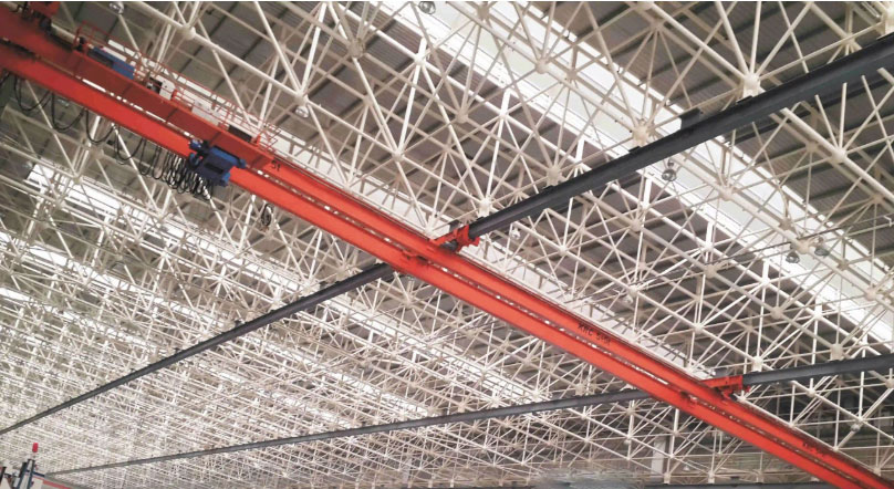
Main beam
main beam shear beam design and the trolley end beam design must have the ability to compensate for problems such as sinking, arching, and deformation of the grid structure caused by thermal expansion and contraction , to ensure that the crane can be used normally under the above conditions .
End beam
The end beam running wheels of multi-point suspension cranes are made of wear-resistant ductile iron or engineering plastics, thus reducing the wear of the running wheels and trolley tracks.
The end beam wheel adopts a single wheel rim structure with guide wheel design, which ensures smooth operation.
Independent friction drive wheels transmit the drive force to the track and are not affected by the load.
Guide wheel devices are installed at both ends of the end beam to avoid rail gnawing .
The high friction coefficient between the driving wheel and the track prevents the running wheel from slipping.
Easy to assemble and maintain.
General electrical protection
Conventional electrical protection: zero position, overcurrent, overvoltage, undervoltage, short circuit, overheating, grounding, etc. The metal structure on the crane, the metal casing of the electrical equipment, the guide rails and other parts are reliably grounded.
Lifting mechanism
Motor reducer three-in-one design, compact structure, light weight , energy saving, maintenance-free , high reliability
Motor – squirrel cage asynchronous motor, synchronous speed, heavy duty, duty cycle 60% ED, optimized air cooling ( cooling increased by 30%)
Motor protection class I F 55, F class insulation
Reducer – sealed, compact, hardened tooth surface, silent design, semi-grease lubrication, maintenance-free
Brakes – electromagnetic disc brakes, self- adjusting brake pads, maintenance-free, heavy-duty, dust-proof
Large diameter drum, high-strength steel wire rope, four-point limit switch, humanized hook design, safety monitoring unit
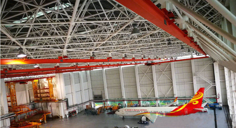
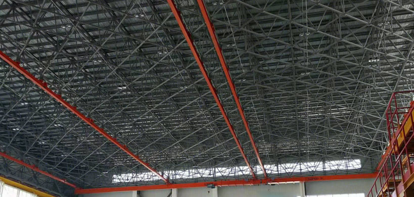
Multi-point crane application scope:
for aerospace industry, airport maintenance cranes
Aircraft manufacturing, aircraft maintenance, aircraft repair
with multiple support points and a span of up to 90 meters offer an efficient solution
Optimize deadweight and reduce the load on the superstructure of the plant
Low headroom for ideal hook height
High-altitude handling and the overhanging design of the internal main beam can fully utilize the available space
Through the crane interlocking system, different working areas can be connected to each other
1 Detailed technical requirements
1.1 Main technical requirements of equipment
1.1.2 The crane should be equipped with an anti-sway system to ensure that when the trolley is running, the swing amplitude is ≤ 20cm when any weight within the rated load moves at the rated maximum speed .
1.1.3 The crane shall have the functions of power failure protection, overload protection, phase loss and phase mismatch protection of the main contactor, lifting height limit (two different types of height limit devices shall be installed at the same time, such as any two of the heavy hammer type, fire-off type, pressure plate type height limiter, etc., except for the transmission type height limiter) and running stroke limit function, power failure emergency locking function, emergency stop function, buffer, end stop , and anti-collision function with other cranes on the same track.
1.1.4 When the lifting weight exceeds 105% of the rated lifting load, the lifting limiter will immediately cut off the power in the overload direction, the lifting equipment will send out an overload alarm signal, and then cut off the upward movement, but the mechanism can move in the downward direction.
1.1.5 Travel limit: The trolley and the car have electrical limit and mechanical limit. The mechanical limit switch safely limits the movement of the crane to the end. The travel of the trolley and the car realizes the primary and final limit. It has the function of anti-collision limit and crane speed limit.
1.1.7 The equipment complies with AQ/T7009 “Standardization Specification for Safety Production of Machinery Manufacturing Enterprises”
* 1.2.4 The track span of all cranes should be measured on site before processing, and the reasonableness of the crane size should be verified based on the actual situation on site before equipment production.
* 1.2.5 The track load capacity shall meet the full load working requirements of all cranes in each span. The specific parameters of the track model shall be designed by the bidder according to the requirements of the bidding documents, but shall not be less than H588*300*12*20 steel. The specific parameters of the track model shall be approved by the design unit of this project and the buyer before it can be put into production.
*1.2.8 Control method: ground hand operator + wireless remote control. by a ground wired control box. The protection level of the remote controller and the control box shall not be lower than IP55 . The remote control and ground wired hand control box are interlocked .
* 1.2.9 Crane power supply introduction method: Use three-phase five-wire single-pole safety busbar, and the safety busbar should run smoothly without jamming. The power supply between the safety busbar and the crane adopts a three-phase five-wire double-powered device, and the power supply from the crane to the electric hoist adopts a highly flexible flat cable. The safety busbar must be a 3C certified product, and the specifications must meet the maximum load requirements of the crane. The power supply contact is good when the busbar is running, and the mounting bracket is firmly fixed without cracks and other welding defects.
1.2.10 Carriage unit:
Trolley frame: The trolley frame is designed as a low-clearance monorail hoist, running on the lower edge of the crane main beam .
The output shaft of the trolley reduction gearbox directly drives the driving wheel, without open gears and maintenance-free.
1.2.12 Electrical safety complies with GB 5226.1, GB/T 5226.32 and AQ/T 7009 provisions.
1.2.13 Electrical control box. The protection level of the distribution box (cabinet, panel) is IP54, in accordance with the provisions of GB / T 4208 .
1.2.14 It is required to select products that meet national energy efficiency rating requirements, such as high-efficiency motors.
1.2.15 Install the power indicator light. The indicator light must be LED type, and one set should be installed at each conspicuous position at both ends of the rail , for a total of two sets.
1.2.16 The crane control circuit must use safe voltage.
1.2.17 Performance testing of lifting equipment in accordance with TSG Q7016 provisions.
1.2.18 After winning the bid , the manufacturer shall coordinate the crane parameters with the design unit, including the large wheel layout, wheel pressure, deadweight, track span and installation method , etc. , and the design institute shall stamp and approve them and submit them to the buyer for filing.
Operating voltage safety voltage
1.2.20 The crane hook is equipped with an anti-unhooking device
1.2.21 Crane noise : in compliance with Chinese national standards (noise no more than 80dB(A))
1.2.22 The crane is equipped with a fully enclosed anti-leakage device to ensure that the lubricating oil does not leak during use.
21.2.23 The crane has weighing and display functions. The weighing unit is kilograms . The weighing error is ≤ ±5% at rated load . The weighing device has a range of twice the maximum lifting capacity of the crane. When the lifting weight is greater than the rated load, an audible and visual alarm signal will be issued and the lifting circuit will be cut off. The display should be installed in a position that is convenient for ground personnel to observe. A load-bearing display interface is installed at a prominent position of the crane main beam (the display font size is not less than 10 inches )
1.2.24 A safe distance is left between the crane and both ends of the factory building. The specific dimensions shall be confirmed by the crane manufacturer and the design institute in coordination and the structural strength parameters shall be confirmed . After the design institute stamps its approval, it shall be submitted to the buyer for filing.
1.2.25 The measurement units of all crane parts and various instruments should all adopt the International Units ( SI) standards. the design , manufacture, transportation, installation, commissioning and acceptance of the connection base, rails, safety scales, mechanical limits, safety slides, mounting brackets , power supply from the distribution box to the safety slides, and lifting equipment below the steel structure connection plate.
1.2.27 Provide compensation scheme for track deformation, and provide detection scheme and detection results.
1.2.28 The lifting mechanism must be equipped with dual braking devices, one is the motor brake, and the other is the mechanical hoist drum brake. If there is a problem with the motor brake, the drum brake can realize the braking function. The seller must provide the structure and working principle of the drum brake.
1.2.29 The crane end beam adopts double-sided drive wheel or friction drive design, and the wheel has a long service life . It ensures the synchronization of multiple end beams of the trolley, thereby ensuring that the crane trolley does not bite the rails during operation.
The gearbox and friction wheel are maintenance-free design, only need to add lubricating oil regularly to prevent lubricating oil from dripping on other equipment. (See the track installation diagram for details, and there is a steel track wheel device)
* 1.2. 30 The wheel adopts curved surface processing technology to avoid the stress-bearing part of the wheel appearing on the edge of the lower cover. Wheel material: The material used is not less than 42 CrMo steel forgings to increase the service life of the wheel.
1.2.31 The crane has sound and light warning functions when in operation, and the warning volume must be able to be heard by ground operators.
1.2.32 The crane trolley should have an automatic deviation correction function and a solution should be provided.
1.2.33 The hoisting motor should have a large overload capacity and high structural strength, and be suitable for intermittent periodic work, frequent starting and braking, short-term overload and other functions. The braking torque of the brake is twice the rated torque, the braking is reliable, and it has an automatic wear compensation function. The crane has a running cumulative timing function . 1.2.34 When assembling the suspension track, the quality of the steel shape should be checked first. If there is any deformation such as bending or twisting, it should be corrected before assembly. After the crane arrives, check the deadweight , lifting capacity and other related parameters. Construction can only be carried out after verification.
1.2.35 Technical requirements for crane steel structures
*The crane main beam is a welded box-shaped beam, which is required to be light in weight and have high horizontal and vertical stiffness.
The vibration frequency should comply with relevant national standards.
The steel plate material used to manufacture the crane should comply with China’s national standards or relevant international standards and have a quality assurance certificate. The main beam material is Q355B. When the crane is submitted for acceptance, the material certificate or qualification certificate of the steel plate and important parts should be provided. The main beam steel plate material must comply with the relevant national specifications, and the rigidity must meet the requirements of national standards. The main steel structure material should have good welding processability, and the main steel structure material should have a material report and a corresponding qualification certificate. All butt welds are non-destructively tested and a flaw detection report is issued.
The steel structure design of the crane shall fully comply with the steel structure standard of DIN15018 or equivalent international standards for steel structure or crane design.
The crane steel structure design is reasonable, the structure is optimized, and it complies with the specifications and standards, and meets other requirements such as strength, rigidity and stability. The design should fully consider the on-site working environment: the design of the steel structure must take into account the convenience and reliability of manufacturing, inspection, transportation, installation and maintenance. Under the conditions of meeting the needs and relevant current specifications and standards, the use deformation of the steel structure is minimized through optimized design.
The steel structure of the crane is mainly composed of the main beam, end beam, etc. The main beam is a box-shaped structure; buffers are set at both ends of each end beam, which cooperate with the trolley travel photoelectric switch.
The external inspection of steel structure welds shall not contain cracks, holes, solid slag, lack of fusion, lack of penetration, shape defects and other defects. The main welds must be subjected to non-destructive radiographic testing and a flaw detection report must be issued.
The main beam is welded by gas shielded welding, and all welds are required to be 100% inspected by nondestructive testing and meet the requirements of the specifications.
The crane main beam is an important load-bearing component of the crane. Each main beam should be made strictly according to the manufacturing process standards from cutting to welding, and the design of the main beam fully meets the requirements of strength, rigidity and stability. The main beam should be designed and manufactured with consideration of the camber, and special equipment should be used to form the camber in one step during processing. The camber of the completed main beam is ensured to be LK/1000-1.2LK/1000 ( LK is the span of each section of the crane ) . The maximum camber value is controlled within the range of LK/10 in the mid-span. The initial camber during the assembly of the main beam and the camber included in the deadweight after the installation of the multi- point suspension crane are determined, which must comply with GB/T14405-2011 “General Bridge Crane” and other current relevant standards. The crane trolley running track adopts the national standard H steel track.
The relative difference of the diagonal of the crane main beam (single span) should be less than 3mm, the difference in the center distance of the two main beams (hoisting trolley gauge) should be less than ±3mm, and the connection gap between the lower flanges of the steel rail should be average and should be guaranteed to be within: ± 3mm.
Before the crane leaves the factory, anti-rust measures should be taken on all exposed processed surfaces. During shipment , metal surfaces should be protected to ensure that the appearance of the equipment is not damaged.
The main beam connection of the multi-point suspension crane adopts an articulated type, and the end beam connection adopts high-strength bolts to avoid the occurrence of three- legged phenomenon and ensure reliable operation.